|
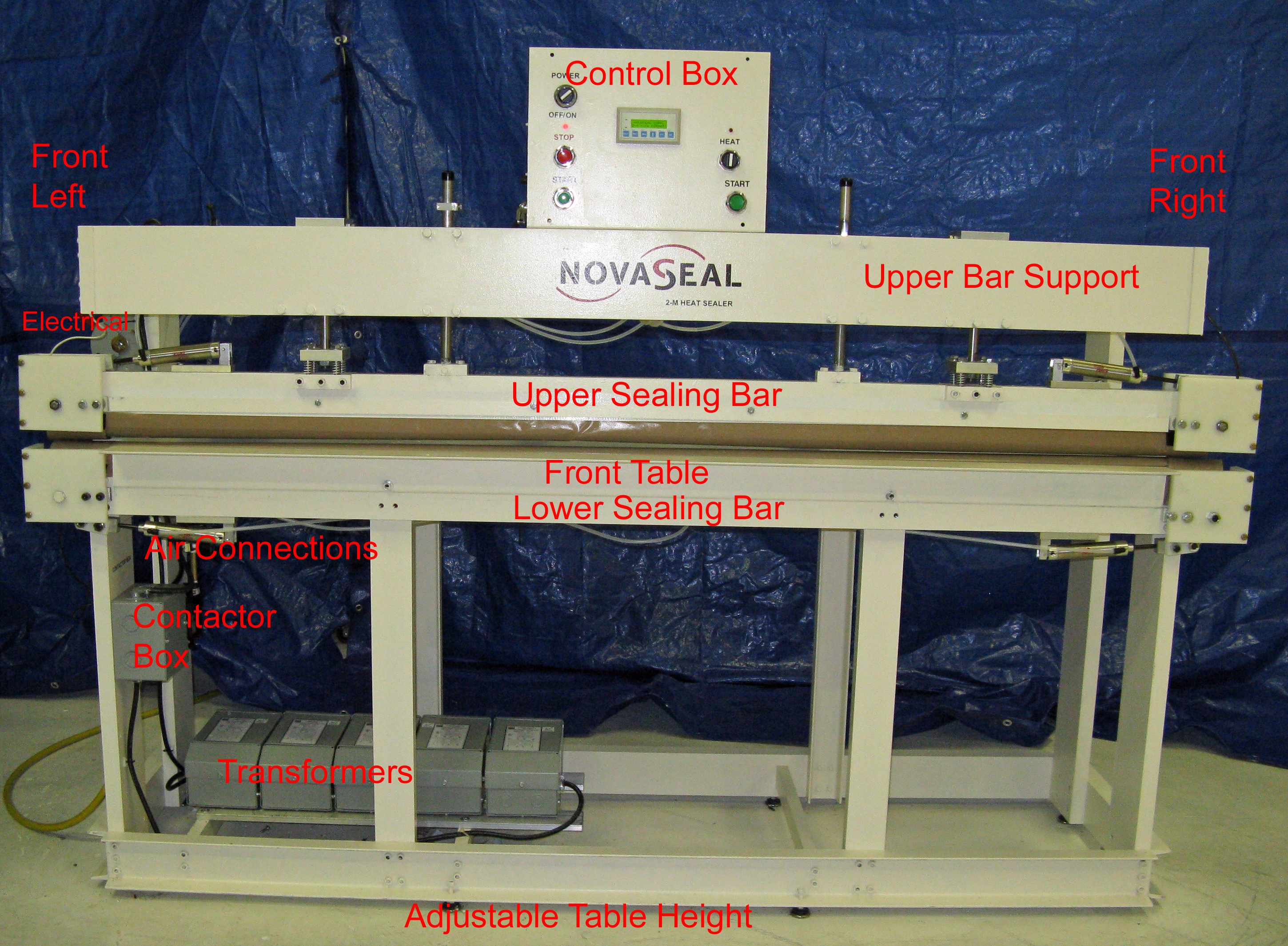 Naming Convention, also known as nomenclature is used to define terms referred to in the Operating Instructions, etc. Also, if you call Novaseal for any reason, please use our naming conventions when referring to components of this machine. Naming Convention, also known as nomenclature is used to define terms referred to in the Operating Instructions, etc. Also, if you call Novaseal for any reason, please use our naming conventions when referring to components of this machine.
The photo shown to the left is taken of the FRONT of the machine. Machine RIGHT is to the right of the photo. Machine LEFT is the left side of the photo.
From top to bottom. Control Box sits on top of the machine. Below the Control Box is the Upper Bar Support.
The 2 Pneumatic Cylinders sit on cylinder plates attached to the Upper Frame Structure. On the other end of the Pneumatic Cylinders or Press Cylinders is the Upper Sealing Bar. Below the Upper Sealing Bar is the Lower Sealing Bar and Table. On the bottom of the machine and oriented to the left side of the machine is the Transformer section. Transformers provide sealing power. Contactor is a high powered relay that switches the Transformers on and off based on the programmed pulse bandwidth. Contactor makes a slight switching noise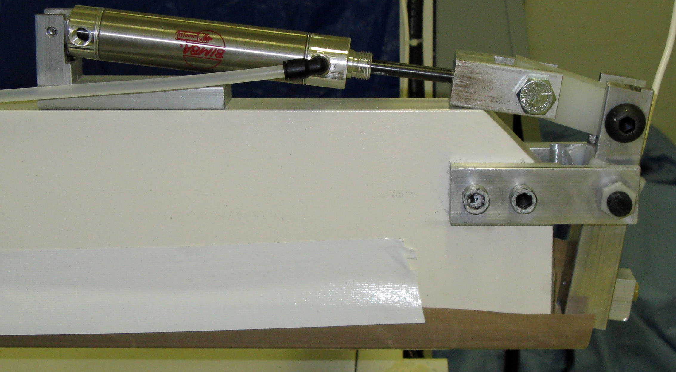 . .
ROCKER Assembly. There are 4 Rocker Assemblies. One on each end of the Sealing Bars. The ROCKER Assembly assures that the I-Wire is always under pressure. Make sure that the Air Switch is always ON. The Air Switch located near the Machine Air Inlet (Left Side of Machine) must remain on at all times especially when the machine is sealing. Shown here is right side upper bar ROCKER without safety cover.
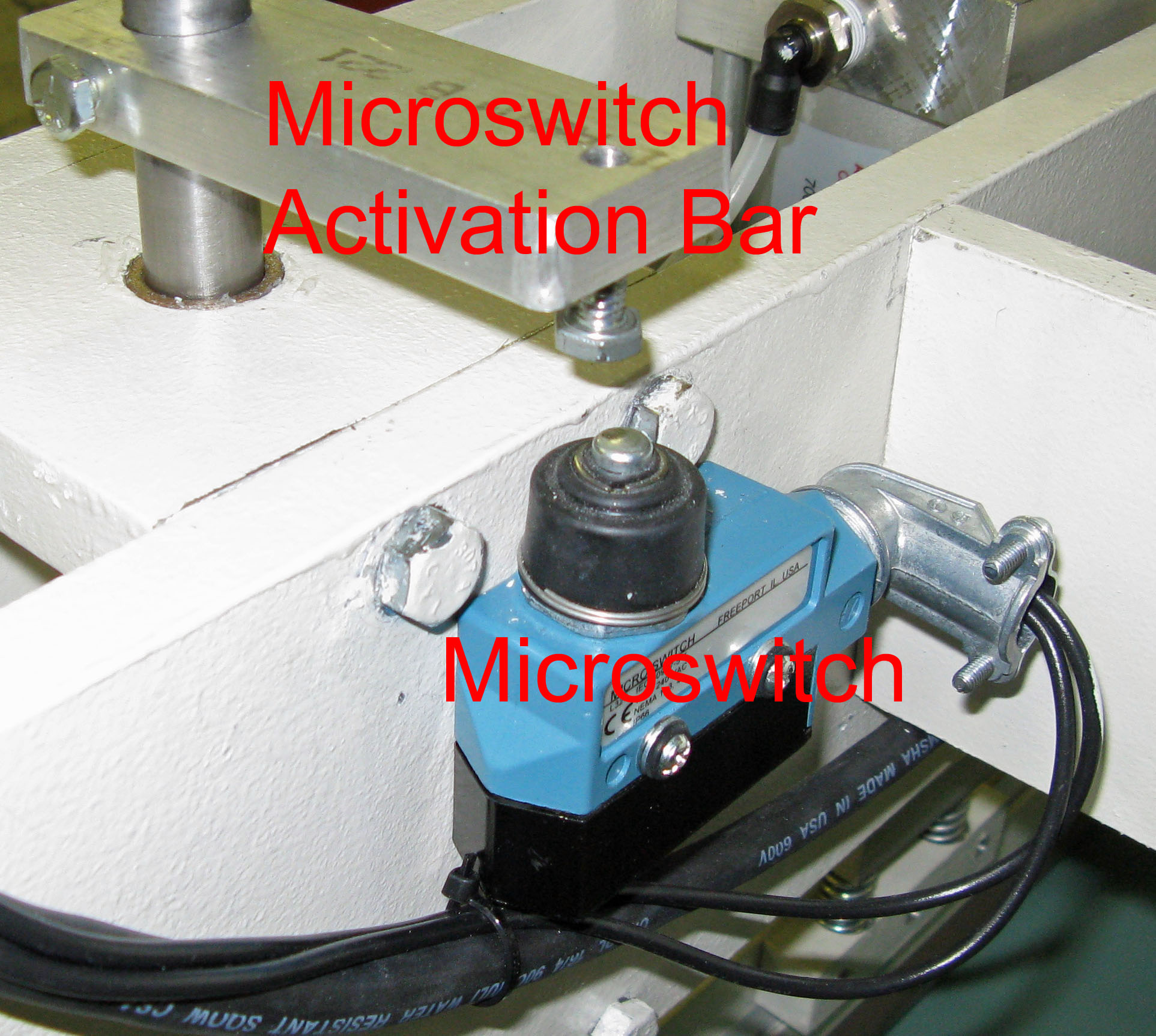 MICROSWITCH. Heat Sealing begins when the microswitch is depressed as shown in the photo on the left. MICROSWITCH. Heat Sealing begins when the microswitch is depressed as shown in the photo on the left.
The Microswitch Activation Bar is positioned on the Alignment Rod such that when the Upper Sealing Bar is in the DOWN position, the I-Wires are automatically energized by the Microswitch input signal.
If everything has been set to seal, and you don’t get a seal, then check to assure that the Microswitch is depressed by the Microswitch Activation Bar when the Upper Sealing Bar is in the DOWN position as shown in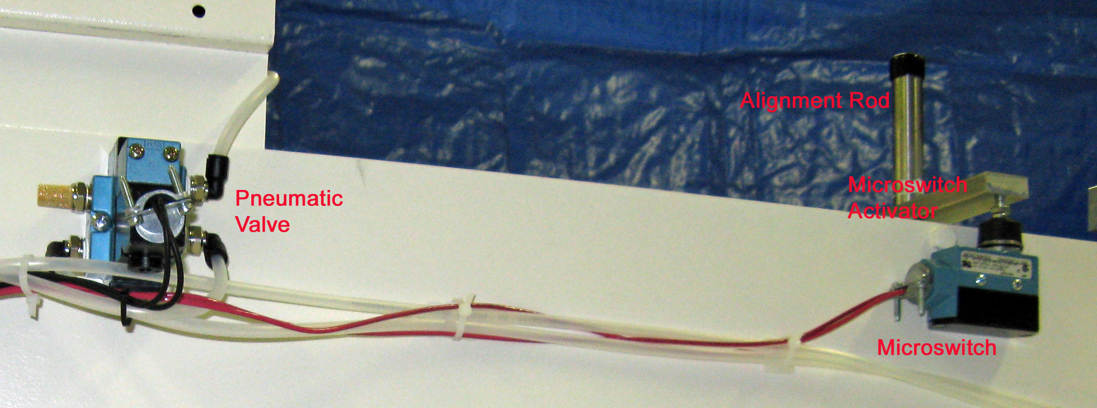 the photo to the right. If the Microswitch Activation Bar set screws become loose, the Microswitch Activation Bar could reposition and not activate Microswitch when in the down position. the photo to the right. If the Microswitch Activation Bar set screws become loose, the Microswitch Activation Bar could reposition and not activate Microswitch when in the down position.
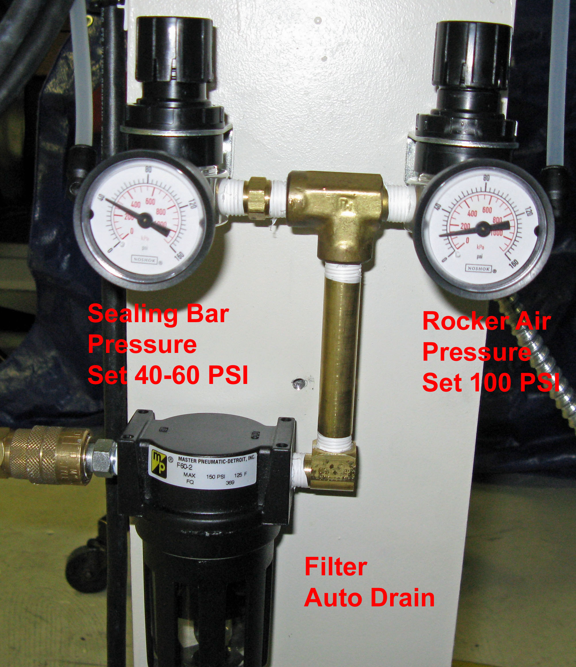
COMPRESSED AIR INLET
Attach Female Quick Disconnect to the male fitting to the left of the FILTER in the photo on the left. The compressed air inlet is located on the left side of the machine on the inside back leg.
Also shown in this photo is the Regulators for Sealing Bar air pressure and Rocker air pressure.
Rocker air pressure must always be greater than Sealing Bar air pressure. Ideal ranges for each: Sealing Bar, 40-60 psi; and Rocker, 100 psi.
Filter includes an auto drain valve.
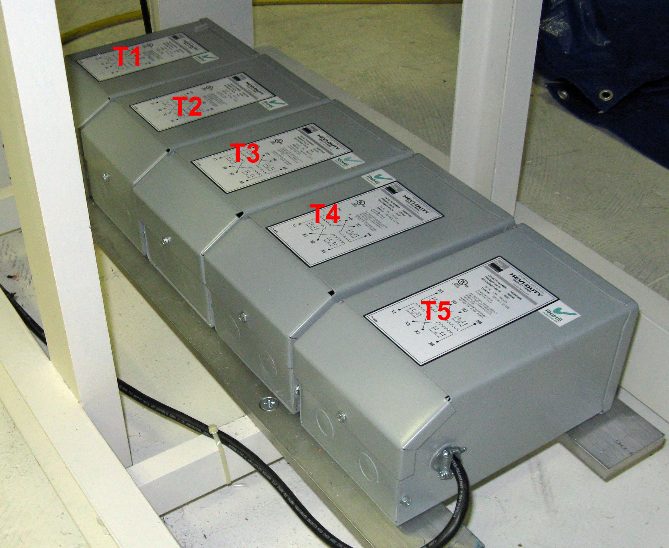
TRANSFORMERS.
The transformer section is located on the bottom of the machine and near the left side of the machine. Transformers are numbered from Left to Right, T1 through T5. If additional 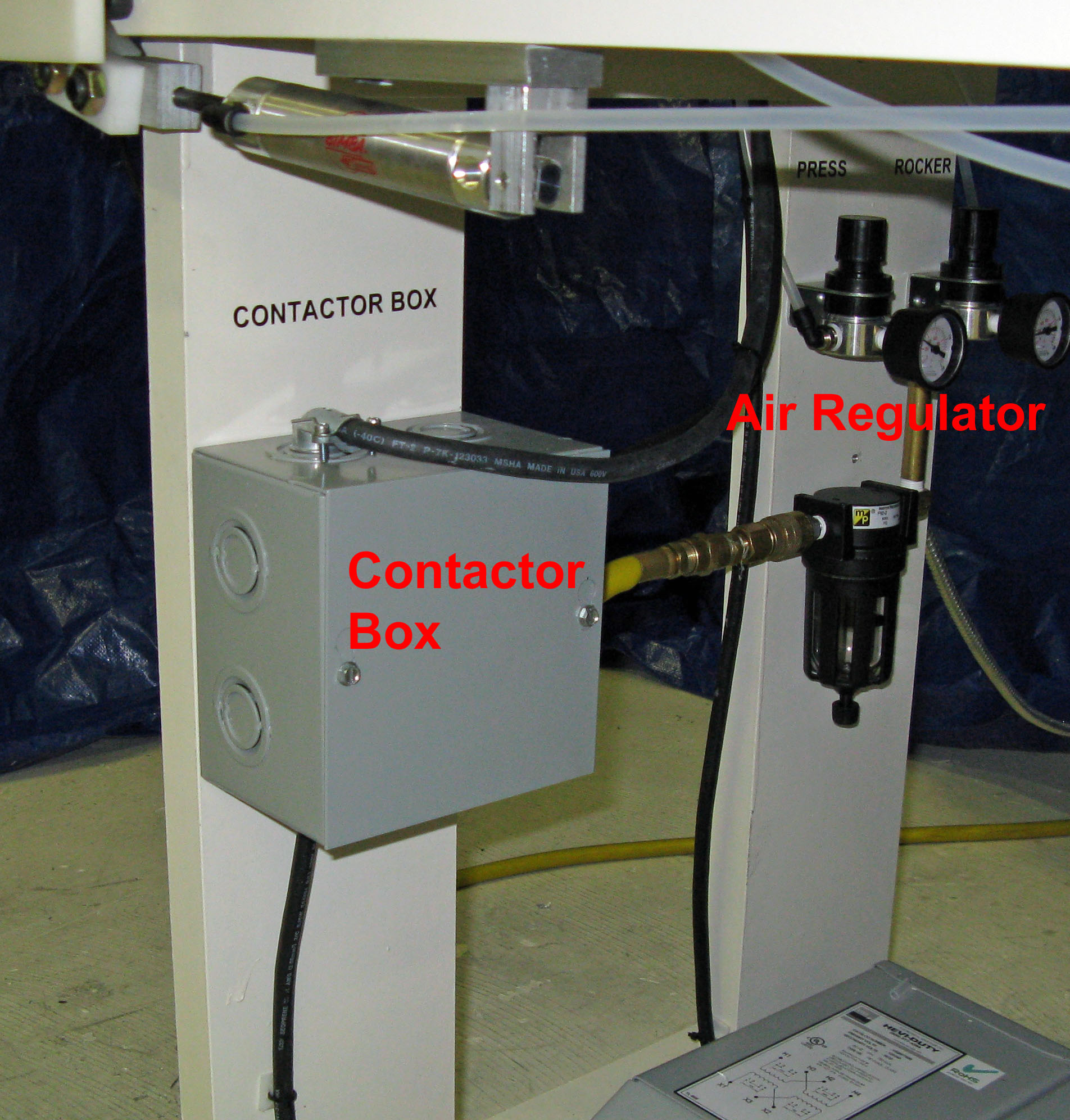 power is needed, add additional transformer(s) to the right side of T5, although this machine is already configured with PowerPak for additional power. power is needed, add additional transformer(s) to the right side of T5, although this machine is already configured with PowerPak for additional power.
The Contactor is a high amperage relay and is placed between Safety Switch and Transformer array. The Contactor is automatically switched by the Control Box PLC
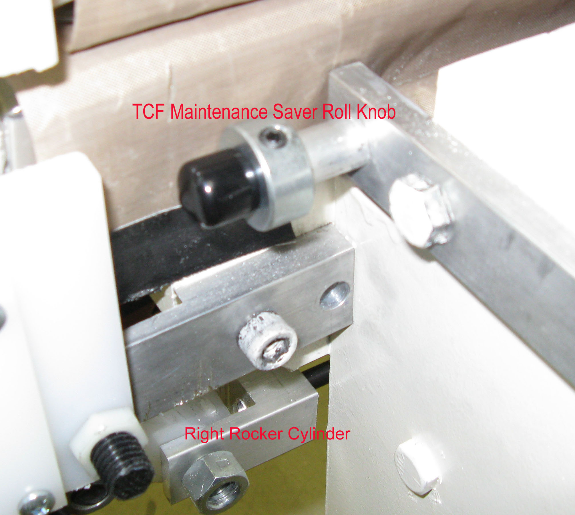 TCF MAINTENANCE SAVER. TCF MAINTENANCE SAVER.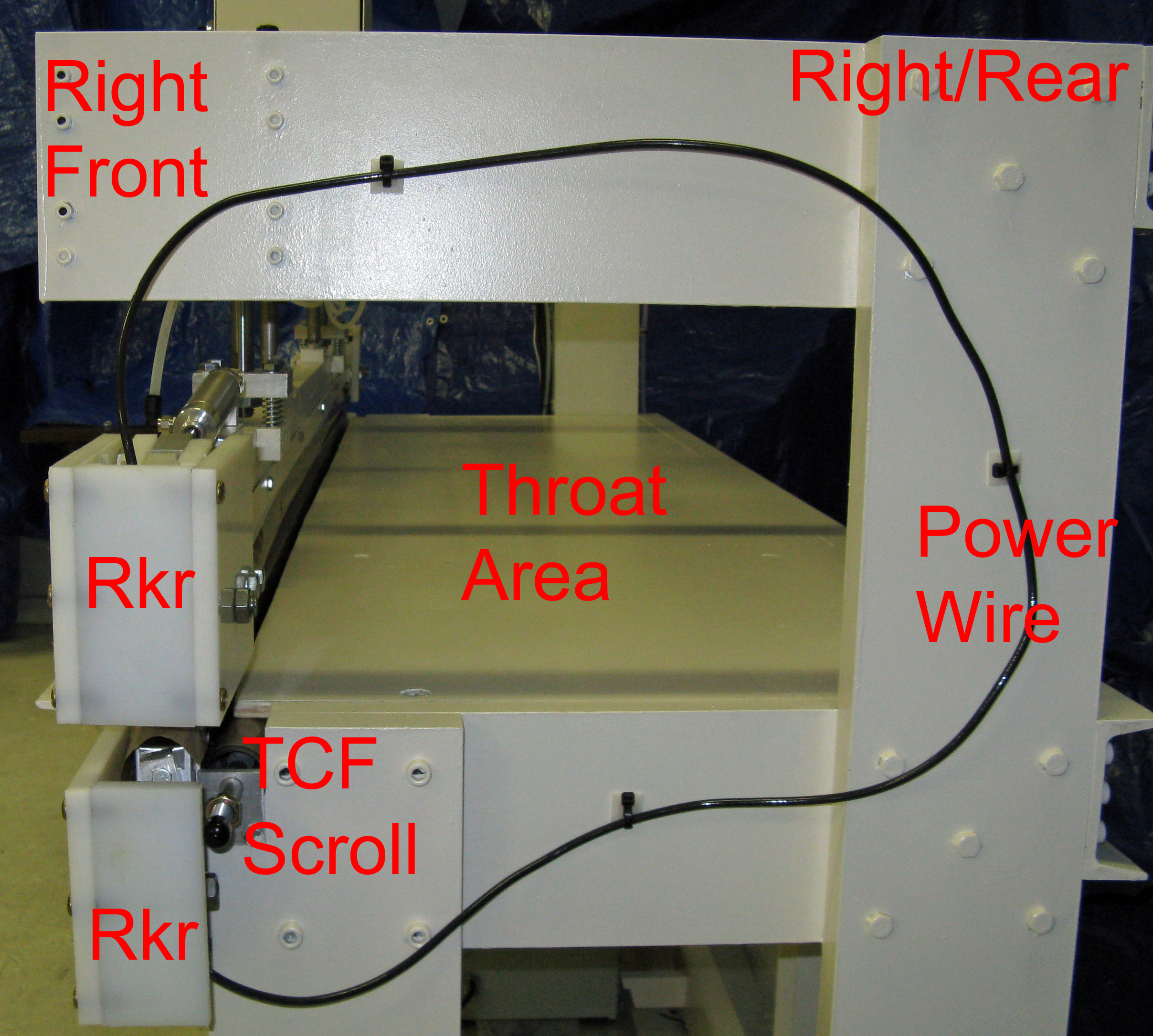
TCF Maintenance Saver feature is added to the Lower Sealing Bar. Use the Collar to rotate new TCF material into the machine.
THROAT AREA.
Photo on the right shows the Throat area as seen from the Right side of the machine.
Also shown in this view is the Power Wire. This wire connects the I-Wire Rocker from the Upper Sealing Bar to the Lower Sealing Bar. The impulse wires are in series. Use the Throat Area to store material used in the sealing process.
AIR SWITCH
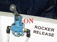 Air Switch is located back left upper side of the Machine. In these photos Air Switch is located back left upper side of the Machine. In these photos 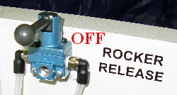 two positions of the Air Switch are shown. The left photo shows the Air Switch ON (45-deg UP). The right photo shows the Air Switch OFF (90-deg DOWN). two positions of the Air Switch are shown. The left photo shows the Air Switch ON (45-deg UP). The right photo shows the Air Switch OFF (90-deg DOWN).
The Air Switch is only used to assure continous air pressure on the ROCKER Assembly. The Air Switch must always be ON when machine is used for sealing. The only time the Air Switch should be turned OFF is when replacing I-Wire(s).
|